



A poorly selected valve manifold can create unstable readings, extra leak points, difficult maintenance, and unsafe isolation around pressure instruments. The solution is not simply adding more valves. You need the right manifold configuration, materials, pressure rating, connections, and test strategy for the application.
A valve manifold is a compact assembly that combines two or more valves into one body to isolate, equalize, vent, bleed, or route process pressure. Common designs include 2-valve, 3-valve, and 5-valve manifolds. They are widely used with pressure gauges, pressure transmitters, and differential pressure instruments because they simplify fluid control while reducing separate fittings and potential leak points.
What Is a Valve Manifold and How Does the Valve Assembly Work?
A manifold puts several fluid-control functions into one compact unit. Instead of installing a separate isolation valve, equalizing valve, bleed valve, tubing, and several adapters, engineers can combine these functions within a single valve manifold.
The exact assembly depends on its job. Some manifolds isolate a pressure gauge from the process line. Others connect a pressure transmitter or differential pressure transmitter to high- and low-pressure process connections. The internal flow path lets an operator isolate, equalize, bleed, or vent pressure in a controlled sequence.
This design is especially useful in instrumentation applications because every extra fitting can become a potential leak location.
A simple concept diagram looks like this:
Process
│
▼
Block Valve
│
├──── Manifold Body ──── Pressure Instrument
│
Bleed / Vent
│
▼
Safe Discharge
A more complex differential-pressure arrangement may contain two block valves, one or more equalizing passages, and dedicated vent valves.
The result is a compact assembly that can make installation and service easier while reducing external tubing.
Why Use a Manifold Valve Instead of Separate Valves and Fittings?
Imagine connecting five individual valves with several pieces of tubing, adapters, tees, and threaded connections. The system may work, but every additional connection creates another location that must be installed, inspected, and maintained correctly.
A manifold valve reduces this complexity by integrating several functions into a single body. Fewer external connections can mean a smaller installation footprint and fewer possible leakage paths.
| Design consideration | Separate valve arrangement | Valve manifold |
| Components | Multiple independent parts | Integrated assembly |
| External fittings | Usually more | Usually fewer |
| Installation space | Larger | More compact |
| Leak points | Potentially more | Can be reduced |
| Instrument isolation | Depends on piping | Integrated |
| Equalizing function | Requires extra valve | Available in selected manifolds |
| Vent function | Added separately | Can be integrated |
| Maintenance access | Installation-dependent | Centralized |
This does not mean a manifold automatically improves every system. Engineers still need to evaluate flow rate, operating pressure, temperature, media compatibility, allowable pressure drop, maintenance access, and the required types of valves.
For industrial fluid control, simplicity is useful only when the equipment is correctly selected.
What Are the Main Types of Manifolds?
There are many types of manifolds, but pressure instrument manifolds are commonly grouped according to the number and function of their valves.
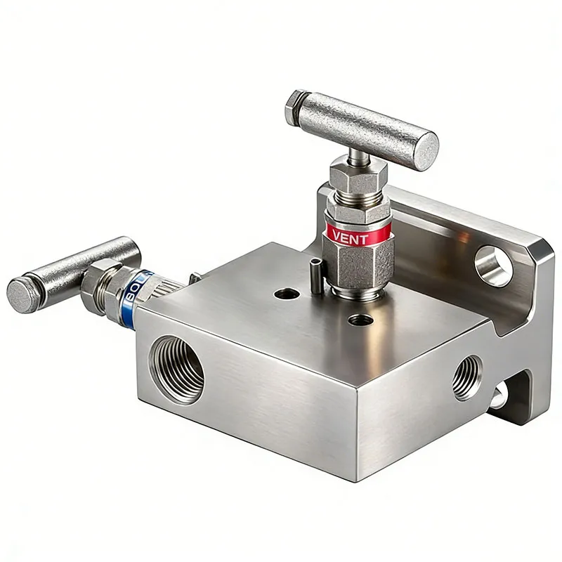
A 2 valve or 2-valve configuration commonly provides isolation plus vent or bleed functionality. It is often associated with gauge-pressure and transmitter installations where equalization between two process sides is unnecessary.
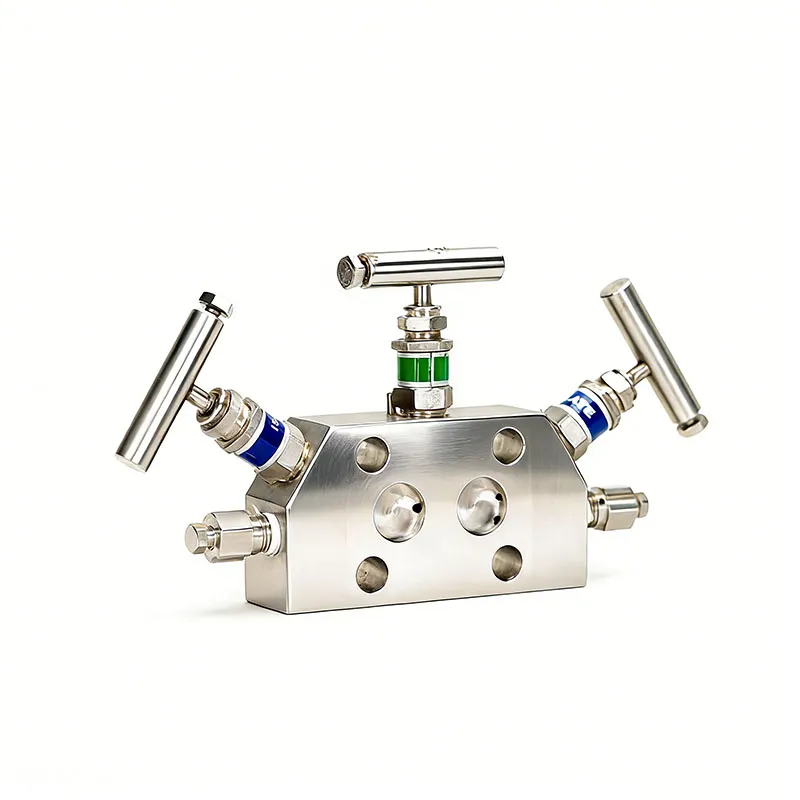
A 3 valve or 3-valve manifold commonly contains two isolation valves and one equalizing valve. It is widely associated with differential-pressure measurement.
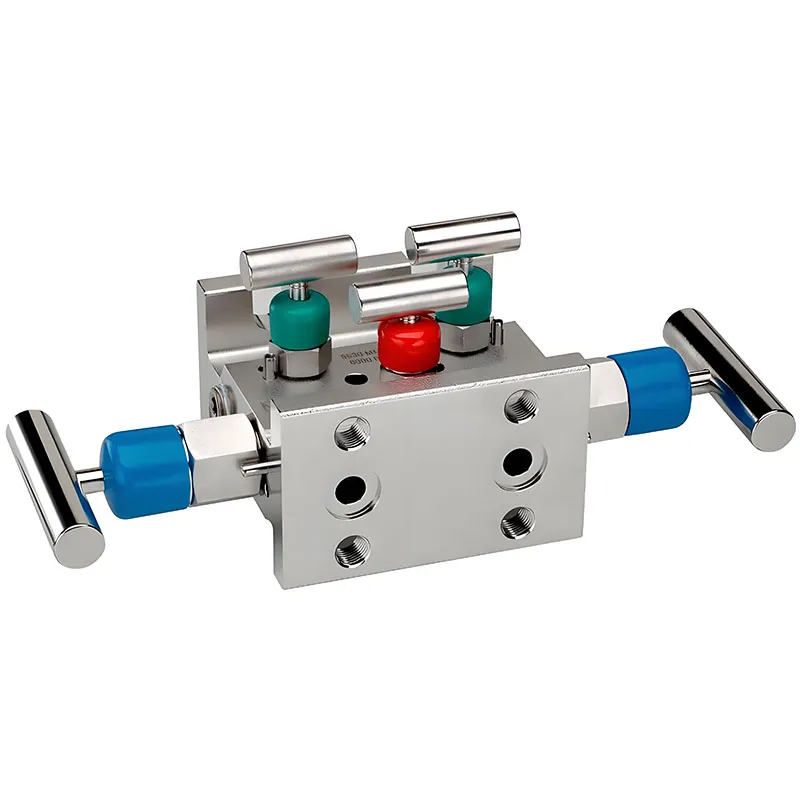
A 5 valve manifold typically expands the three-valve concept by adding dedicated bleed or vent functions. A 5-valve manifold therefore provides more control during isolation, equalization, venting, testing, and certain calibration procedures.
A simplified comparison is:
| Configuration | Typical functions | Common instrument |
| Two valve | Block + bleed/vent | Gauge or pressure transmitter |
| Three-valve | Two block + equalize | Differential pressure transmitter |
| Five-valve | Two block + equalize + two bleed/vent | DP transmitter/testing applications |
The important point is that the number of valves alone does not define suitability. Port arrangement, pressure rating, media, materials, sealing structure, and fitting specifications must also match the process.
How Does a 2-Valve Manifold Work with a Pressure Transmitter?
A two-valve design is one of the simplest manifold arrangements. It commonly combines a block valve with a vent or bleed function.
The block function can isolate the transmitter from the process. Once proper isolation has been established, the second valve can support controlled pressure release according to the system procedure. This arrangement is useful where the instrument measures gauge pressure rather than differential pressure.
For example, a pressure instrument may read process pressure relative to atmospheric pressure. The manifold provides an organized interface between the instrument and the process rather than relying on a collection of individual components.
The operator still needs to follow the correct valve sequence. A manifold does not remove the hazards of pressurized fluid. Before disconnecting a gauge or transmitter, technicians should verify isolation and confirm that trapped manifold pressure has been safely relieved.
This becomes increasingly important in high pressure systems.
When Should You Use a 3-Valve Manifold?
A three-valve manifold is strongly associated with differential pressure measurement.
A typical configuration includes:
- one high-side isolation valve;
- one low-side isolation valve;
- one equalizing valve.
The two isolation valves connect the process to opposite sides of the differential pressure transmitter. The equalizing passage can connect the two sides when the procedure requires them to equalize.
Why does this matter?
A differential pressure instrument responds to the difference between two pressures. During startup, shutdown, maintenance, or calibration, an uncontrolled pressure difference can produce misleading measurements or expose the sensing element to unwanted loading.
The manifold gives technicians a controlled way to manage pressure and differential pressure around the instrument.
However, valve sequence matters. Opening and closing the wrong valve at the wrong time can create an unwanted pressure condition. Operators should therefore follow the instrument manufacturer’s procedure and the site’s approved operating method rather than assuming every 3-valve system uses exactly the same sequence.
How Does a 5-Valve Manifold Improve Differential Pressure Control?
A five-valve arrangement adds functionality to the standard three-valve concept. A common configuration contains two isolation valves, an equalizing function, and two bleed or vent valves.
That makes 5 valves available for managing the instrument circuit.
The extra valves can make controlled depressurization, verification, and calibration work more convenient. For technicians working around a differential pressure transmitter, this additional control can be valuable.
But more valves also mean more internal sealing points. A 5-valve design therefore needs good manufacturing consistency, reliable needle-valve sealing, suitable materials, and appropriate pressure verification.
In demanding service, buyers should not judge a 5 valve manifold only by its outside appearance. Ask about working pressure, test pressure, connection standard, valve-seat design, media compatibility, temperature limits, and testing requirements.
Why Are Needle Valves Common in Instrument Manifolds?
Many instrumentation manifolds use needle valves because their stem and seat geometry can provide controlled shutoff in compact pressure systems.
This matters because instrumentation is not the same as a large process pipeline. A pressure instrument often handles a relatively small fluid volume, yet small changes can affect the measurement. Controlled valve operation helps technicians manage isolation and vent functions more carefully.
The design must still match the medium. Water, hydraulic oil, compressed gas, and aggressive process fluids can require different wetted materials and sealing choices.
Common body-material considerations may include stainless steels or carbon steel, depending on service requirements. The correct material should be selected from actual process conditions rather than from price alone.
Likewise, pressure drop and heat, corrosion, temperature, vibration, and pressure fluctuation can influence long-term performance. For critical applications, the complete valve-and-instrument interface deserves engineering attention.
Direct-Mount vs Remote-Mount Valve Manifold Configuration: Which Is Better?
A manifold can be installed in several different configurations. Two common approaches are direct mounting and remote mounting.
A direct-mount manifold attaches closely to the transmitter or other instrument. This can create a very compact installation and reduce external tubing. It is useful when space is limited and the process environment permits the instrument to sit near the tapping point.
A remote-mount arrangement places the instrument away from the process connection and uses tubing between the process and manifold/instrument system. Mounting bracket kits may be used to support the assembly.
| Factor | Direct mounting | Remote mounting |
| Tubing length | Short | Longer |
| Installation size | Compact | More flexible |
| Instrument location | Near process | Can be separated |
| Accessibility | Depends on process location | Can improve access |
| Vibration/heat separation | Limited | Potentially better |
Your decision should consider access, vibration, process temperature, environmental exposure, tubing length, instrument protection, and maintenance requirements. The selected flange, threaded port, tubing fitting, and other process connections must also match the system.
How Do Fittings, Flow Rate, and Pressure Affect Valve Manifold Selection?
A manifold that fits physically may still be wrong technically.
Start with pressure. The selected valve assembly must suit the specified operating and test conditions. For high-pressure systems, body strength, valve construction, seals, connections, and pressure verification all become important.
Next, evaluate the medium and required flow rate. Instrument manifolds normally serve measurement and isolation functions rather than high-volume process transfer, so their internal passages should be evaluated accordingly.
Buyers should define at least these parameters before requesting a quotation:
- Working pressure and required test pressure
- Test or process medium
- Operating temperature
- Number of valves
- Required manifold configuration
- Port and fitting specification
- Instrument connection
- Direct or remote mounting
- Body and wetted materials
- Required pressure-test or leak-test method
- Applicable customer or project specification
- Documentation requirements
This information lets the supplier evaluate the complete manifold system instead of simply matching a product photograph.
How Should a Valve Manifold Assembly Be Pressure Tested?
This question is especially important to us at Highlight / ODMT because our work centers on high-pressure testing equipment and fluid-control systems.
A manifold may be small, but it can contain several pressure boundaries: body passages, threaded or flanged connections, valve seats, stems, plugs, and other sealing interfaces. The required verification depends on the product specification and applicable test procedure.
Depending on the manifold design and project requirements, verification may involve pressure-related and leakage-related checks. The test arrangement must be engineered around the actual manifold rather than assuming one universal pressure value or procedure.
A practical test-system concept may include:
Pressure source → isolation/control → manifold under test → pressure measurement → controlled release
For repetitive industrial production, a customized pressure test system can improve repeatability compared with an improvised setup. Depending on the project, PLC/HMI control, pressure acquisition, pressure-hold monitoring, test records, and automatic test sequences can also be integrated.
Why test-system engineering matters
Suppose a manufacturer produces several manifold configurations:
- 2-valve units;
- 3-valve units;
- 5-valve units;
- different port sizes;
- multiple pressure ranges;
- liquid and gas-service versions.
One fixed fixture may not handle all of them efficiently.
In that case, we look at the entire test requirement: pressure range, medium, fixture design, number of channels, test cycle, accuracy requirement, data collection, safety protection, and production volume. The goal is not merely to produce pressure. The goal is to create a controlled and repeatable testing process.
How Can Manifold Valves Affect Pressure Measurement Accuracy?
The manifold sits between the process and the instrument, so problems within it can influence pressure measurement.
A leaking isolation seat, an equalizing valve that does not seal correctly, trapped pressure, blocked passages, loose connections, or an incorrect operating sequence can all create confusing readings.
For a differential-pressure application, this can be particularly important. If an equalizing path leaks when it should be closed, the measured differential may be reduced. If a vent is not properly sealed, the instrument may respond differently from the real process condition.
Technicians may wrongly suspect the pressure transmitter first.
Before replacing an instrument, inspect the complete pressure path:
Process connection → manifold → tubing/fittings → instrument
This is also why periodic leak checking and instrument calibration should be considered as parts of the same measurement-quality strategy.
Good instrumentation is a system. The sensor alone cannot guarantee accuracy and reliability if the components around it do not maintain the intended pressure boundary.
What Are Common Valve Manifold Problems?
Many manifold problems are simple, but they can have expensive consequences.
Typical issues include leakage around connections, contamination around valve seats, improper valve sequencing, blocked passages, worn sealing surfaces, and fittings that are unsuitable for the pressure or medium.
Pressure fluctuation can make troubleshooting harder because the technician must determine whether the change comes from the process, instrument, tubing, or manifold.
A sensible maintenance approach includes checking:
- external leakage;
- valve operation;
- fitting condition;
- pressure boundary integrity;
- vent and bleed paths;
- equalizing function;
- instrument readings;
- signs of corrosion or contamination.
Never loosen a fitting simply because a pressure reading shows zero. Confirm isolation and safe depressurization first. Trapped pressure can remain inside small cavities even when another part of the system appears depressurized.
That principle becomes even more important as system pressure increases.
What About Sprinkler Valve Manifolds and Other Multiple-Valve Systems?
The term valve manifold is broad. Not every manifold is an instrumentation manifold.
For example, sprinkler valve manifolds distribute or control water across branches in fire-protection or irrigation-related systems. Hydraulic manifolds route hydraulic fluid between pumps, actuators, and control components. Gas manifolds may distribute gas from a common source.
These products can all use a multiple valve concept, but their design purposes differ significantly.
That distinction matters for SEO searches as well as purchasing.
Someone searching for a 5-valve differential-pressure instrument manifold is usually solving a different problem from someone searching for a sprinkler manifold. Pressure, flow, connections, materials, testing standards, and operating logic may all differ.
So when you contact a manufacturer, do not ask only for “a manifold.”
How Do You Specify a High-Pressure Valve Manifold Testing Solution?
For B2B procurement, a useful RFQ should describe both the component and how you intend to verify it.
If you manufacture manifold products, tell us the working-pressure range, maximum test requirement, media, port configuration, production volume, required test cycle, acceptance method, and whether test data must be saved.
At Highlight / ODMT, our broader engineering work covers gas boosting, liquid boosting, valve testing, leak detection, hydrostatic testing, pressure testing, and complete testing-line integration. Depending on project needs, we can develop standalone machines or integrated testing systems with PLC/HMI controls, data acquisition, and customized fixtures.
For overseas industrial projects, we also understand that the machine itself is only part of the decision. Buyers often need to discuss documentation, CE/ISO-related project requirements, operator safety, installation, commissioning, remote diagnostics, training, spare parts, and after-sales support.
Information to send with your inquiry
| Параметр | Example information to provide |
| Product | 2-, 3-, or 5-valve manifold |
| Рабочее давление | Your actual specified range |
| Required test pressure | According to your product/test procedure |
| Medium | Water, oil, gas, etc. |
| Connections | Thread/flange/fitting details |
| Test type | Pressure hold, leakage, functional test, etc. |
| Production demand | Samples, batch testing, production line |
| Управление | Manual, semi-automatic, PLC/HMI |
| Data | Display only or saved test records |
| Fixture | Single model or multiple configurations |
| Compliance | Applicable project/customer requirements |
The more complete these inputs are, the easier it becomes to design the right testing solution without overbuilding the machine.
Valve Manifold Selection Checklist
Before purchasing a manifold or planning its testing process, use this short checklist:
Function: isolation, equalization, venting, bleeding, or distribution?
Configuration: 2-valve, 3-valve, 5-valve, or customized?
Instrument: pressure gauges, transmitter, or differential-pressure device?
Pressure: normal working pressure and maximum required test pressure?
Medium: liquid or gas, and is it chemically compatible?
Connections: thread, flange, tube fitting, or customized interface?
Mounting: direct-mount or remote-mount?
Material: suitable for pressure, temperature, corrosion, and environment?
Testing: how will pressure integrity and leakage be verified?
Automation: is manual testing enough, or is repeatable production testing required?
A good specification saves time at both the purchasing and engineering stages.
Вопросы и ответы
What is the purpose of a valve manifold?
A valve manifold combines several valve functions into one assembly. Depending on the design, it can isolate an instrument, equalize pressure, provide a vent or bleed path, or route fluid between ports. Instrument manifolds are commonly installed between process connections and pressure instruments.
What is the difference between a 2-valve, 3-valve, and 5-valve manifold?
A 2-valve arrangement commonly provides isolation plus bleed or vent functionality. A 3-valve arrangement is often used for differential-pressure instruments and typically adds an equalizing function between two process sides. A 5-valve arrangement adds further vent or bleed capability. Exact layouts should always be confirmed from the manufacturer’s schematic.
Why is an equalizing valve used with a differential pressure transmitter?
The equalizing valve provides a controlled path between the high- and low-pressure sides when the operating procedure requires equalization. This is useful during certain startup, shutdown, maintenance, and calibration operations. Operators must use the correct sequence for the specific instrument and installation.
Can a valve manifold be used in high-pressure applications?
Yes, provided the manifold body, valve design, connections, seals, and materials are rated and verified for the required conditions. Do not select a manifold only by port size or appearance. Working pressure, test requirements, medium, temperature, and applicable specifications must all be reviewed.
How do you test a valve manifold for leakage?
The exact method depends on the manifold design, medium, pressure rating, and applicable product or customer specification. A suitable test setup applies controlled pressure to the required passages while the operator or automated system checks pressure integrity and leakage according to the defined acceptance criteria.
Can Highlight / ODMT customize valve manifold pressure-testing equipment?
Yes. We develop customized high-pressure testing and fluid-control equipment for industrial applications. A project can be configured around the customer’s manifold size, pressure range, medium, test sequence, fixture requirements, production capacity, control method, and data-recording needs. PLC/HMI control and complete testing-line integration can also be considered where required.
 English
 Français
 Русский
 Español
 Português
 العربية
 Tiếng Việt
 한국어
한국어 Bahasa Indonesia
 Deutsch
 Türkçe
 Italiano