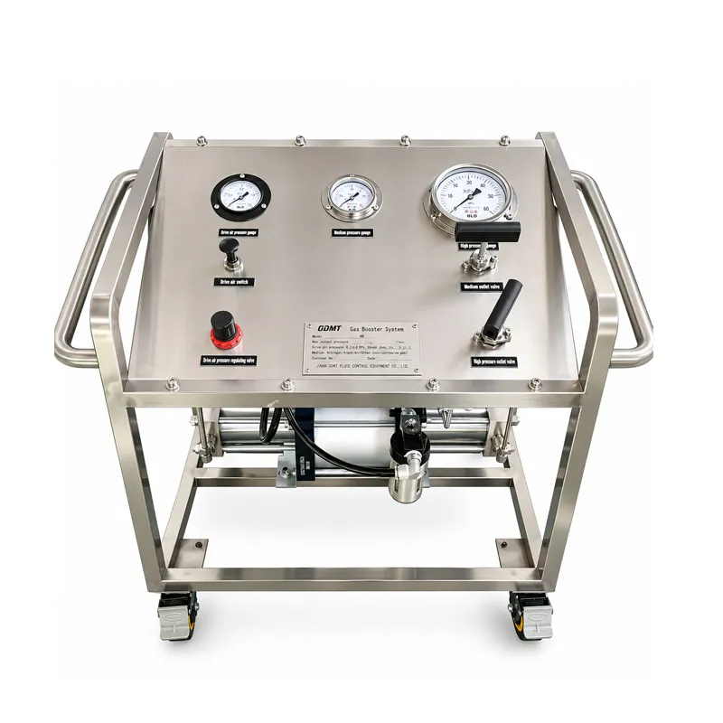
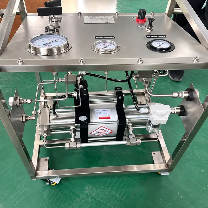
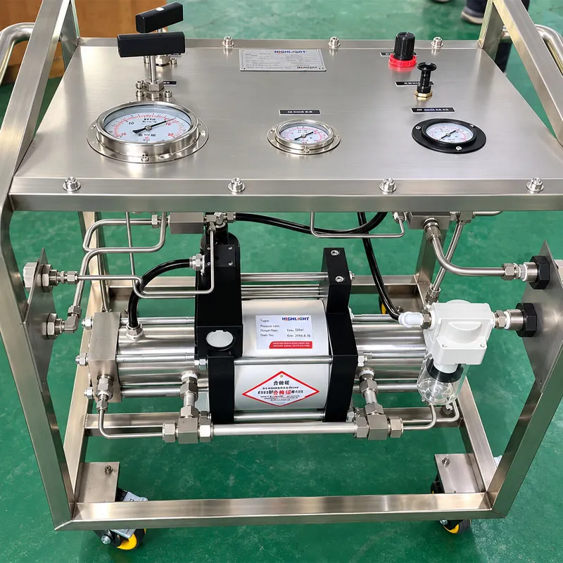
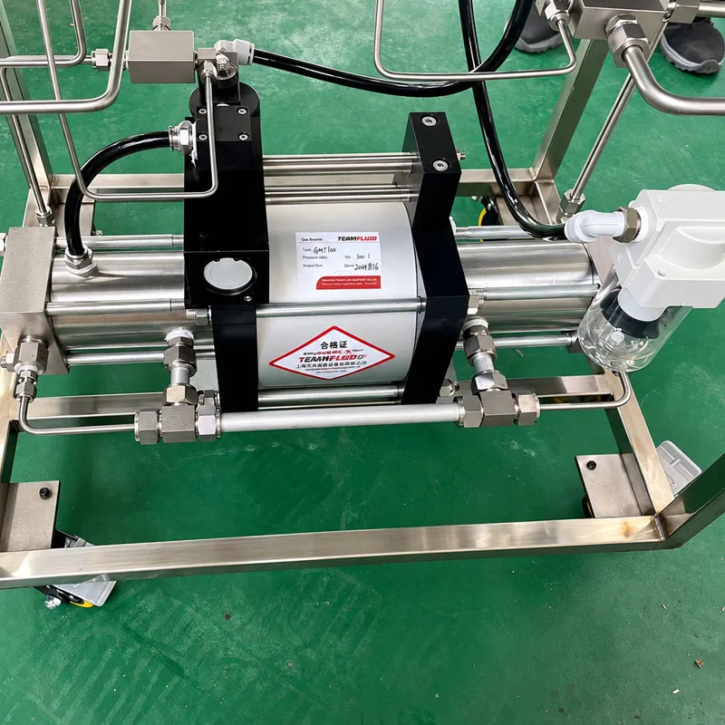
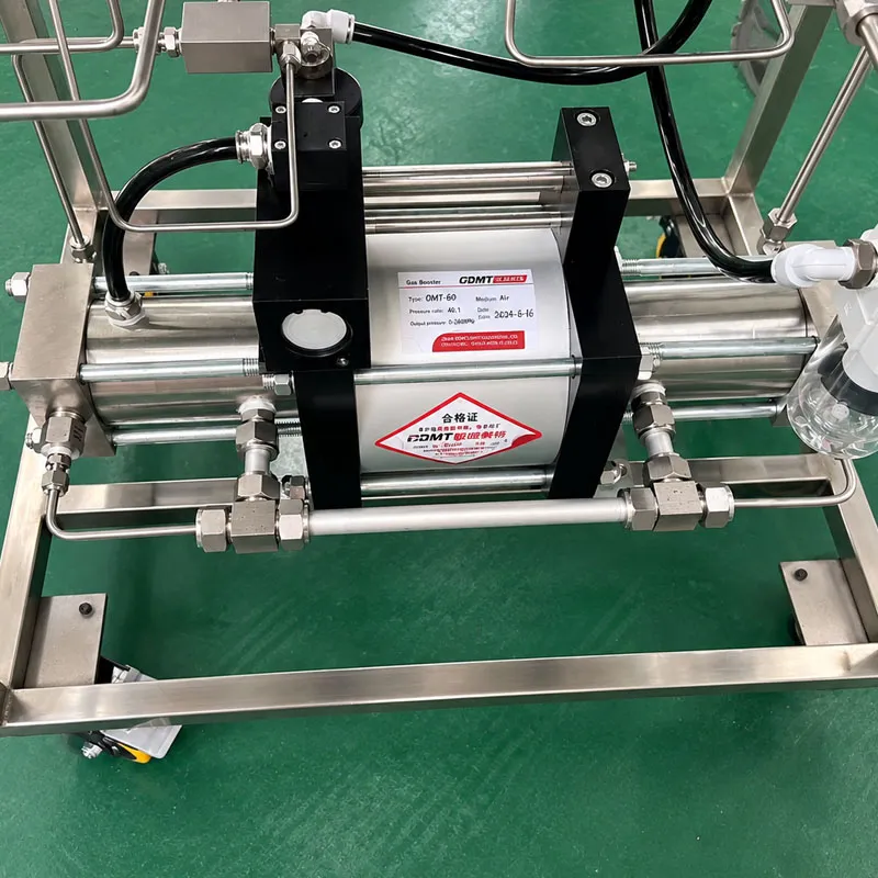
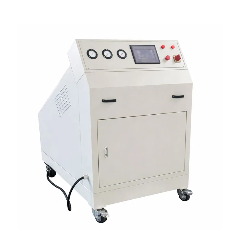
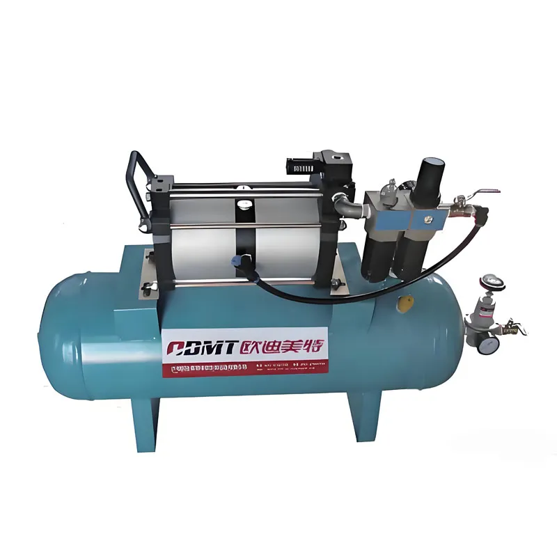
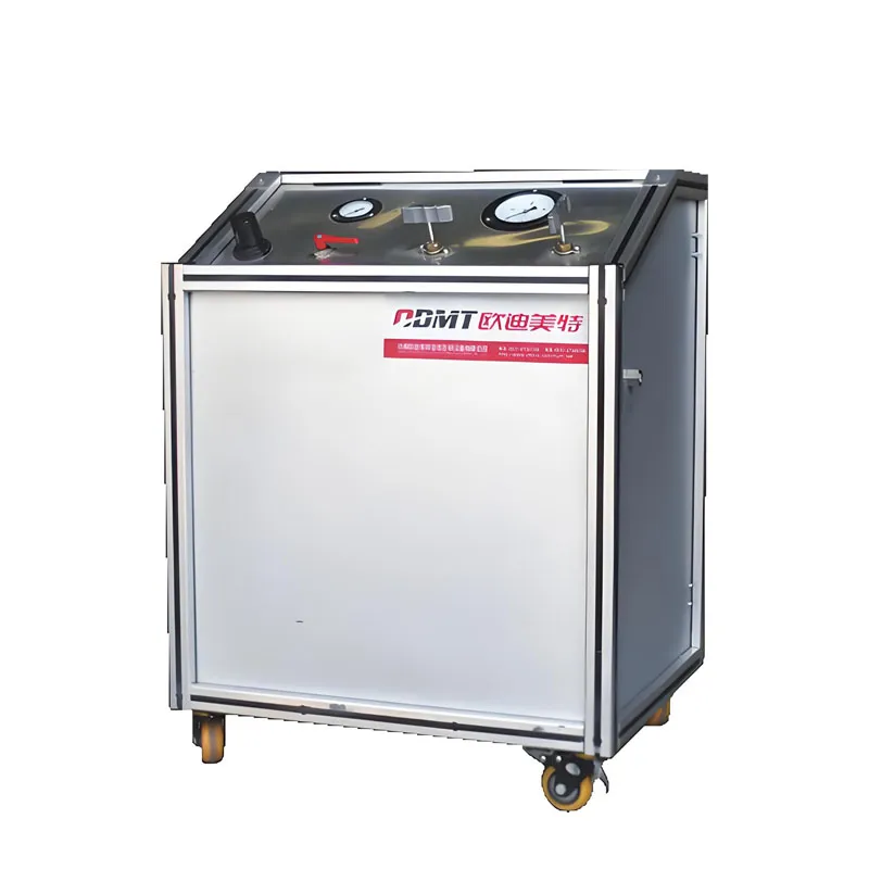
The MGS-OMA40 Frame-Type Gas Booster System combines the gas boosting unit, drive-air treatment components, pressure monitoring instruments and manual controls within an integrated frame.
Compressed air is used as the driving power for the piston-type gas booster pump. During operation, the pneumatic control mechanism drives the booster piston to reciprocate rapidly, continuously compressing the process gas.
As the outlet pressure increases, the reciprocating speed gradually decreases. When the pressure reaches equilibrium, the booster automatically stops. If pressure in the downstream circuit decreases, the booster automatically restarts to compensate for the pressure loss and maintain the required system pressure.
The integrated frame design makes the system suitable for applications where a compact, movable and easy-to-operate gas boosting solution is required.
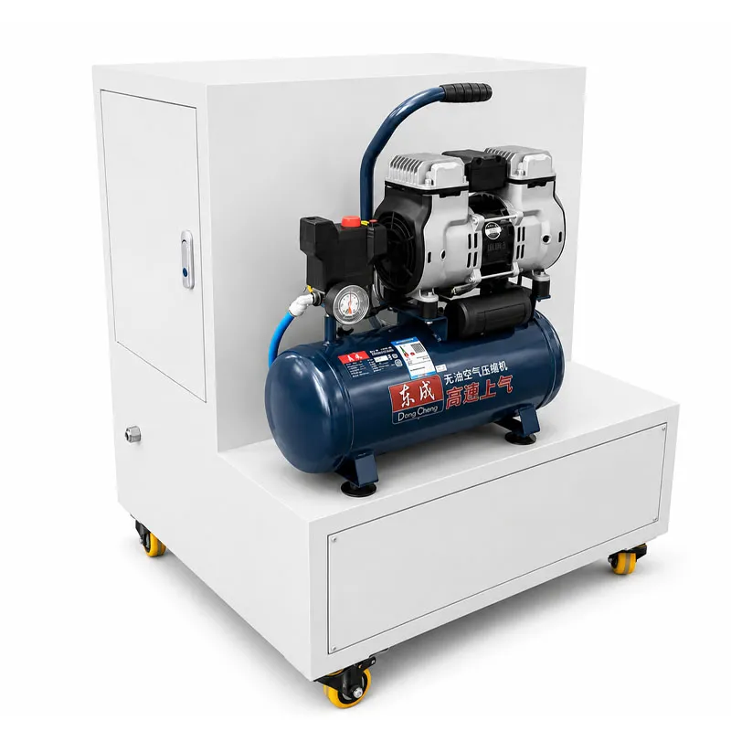
( Picture for reference, we will produce machine according to customers’ requirements.)
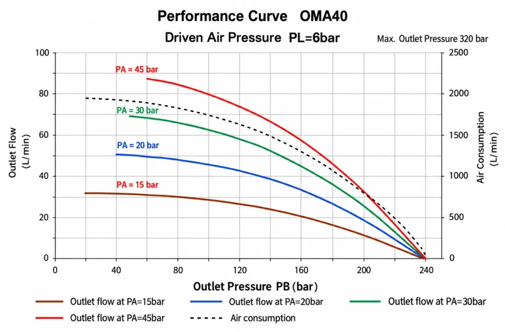
When the inlet pressure is 20 bar (290 psi), the outlet pressure is 130 bar (1885 psi), and the air drive pressure is 6 bar (87 psi)
Flow rate: 42 L/min
| Parameter |
Spécifications |
| Nom du produit |
Frame-Type Gas Booster System |
| System Model |
MGS-OMA40 |
| Booster Pump |
OMA40 Air Driven Gas Booster Pump |
| Booster Medium |
Hydrogen |
| Drive Pressure |
3–8 bar |
| Gas Inlet Pressure |
20–320 bar |
| Maximum Output Pressure |
320 bar |
| Medium Temperature |
Température ambiante |
| Température ambiante |
Température ambiante |
| Output Circuit |
One Way |
| Mode de contrôle |
Manual Operation |
| Pressurization Method |
Pneumatic Pressurization |
| Parameter |
Spécifications |
| Machine Name |
Air Driven Gas Booster Pump |
| Modèle |
OMA40 |
| Booster Medium |
Hydrogen |
| Rapport de pression |
40:1 |
| Maximum Compression Ratio |
20:1 |
| Driven Air Pressure |
1–8 bar |
| Minimum Gas Inlet Pressure |
20 bar |
| Maximum Gas Inlet Pressure |
320 bar |
| Maximum Allowed Outlet Pressure |
320 bar |
| Single Stroke Capacity |
49 ml |
| Maximum Working Frequency |
60 times/min |
| Gas Inlet |
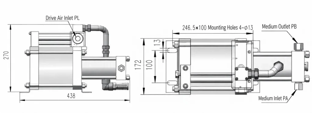
ZG1/2″ (EN ANGLAIS) |
| Gas Outlet |
ZG1/4″ (EN ANGLAIS) |
| Pump Size |
438 × 172 × 270 mm |
| Joints standard |
PTFE, FKM, NBR |
The supplied technical documentation identifies the pump as OMA40 and specifies the above pressure ratio, connections, stroke capacity, operating frequency and seal materials. Pneumatic system quotation 260… Pneumatic system quotation 260…
Reference Operating Point
Under the reference operating condition provided in the technical documentation:
- Gas inlet pressure: 20 bar / 290 psi
- Outlet pressure: 130 bar / 1885 psi
- Air drive pressure: 6 bar / 87 psi
- Flow rate: 42 L/min
Actual flow depends on inlet pressure, outlet pressure and drive-air conditions.
Caractéristiques et fonctions
- Pneumatic Drive – Powered by compressed air for stable gas boosting.
- High-Pressure Boosting – Maximum outlet pressure up to 320 bar.
- Automatic Start & Stop – Automatically responds to pressure changes.
- Pressure Monitoring – Integrated gauges provide clear pressure readings.
- Manual Control – Simple valve operation for convenient system control.
- Air Filtration – Helps keep the drive air clean and reduce component wear.
- Integrated Frame Design – Compact stainless steel frame for easy installation and operation.
Avantages du produit
- Compact Design – Integrated frame structure saves installation space.
- Stable Pressurization – Maintains consistent outlet pressure during operation.
- Reliable Sealing – High-reliability pipelines help reduce gas leakage.
- Low Energy Consumption – Automatically stops when the target pressure is reached.
- Easy Operation – Simple manual controls and clear pressure monitoring.
- Flexible Configuration – Customizable according to gas medium, pressure and flow requirements.
La force de notre entreprise
Highlight se concentre sur la conception et la fabrication d'équipements d'essai de pression et de systèmes d'essai de contrôle des fluides, en prenant en charge à la fois les modèles standard et la personnalisation en fonction des projets.
- Plus de 16 ans d'expérience dans le domaine des équipements d'essai de pression et des systèmes de surpression pneumatique
- Capacité de production annuelle : plus de 1000 équipements
- Plus de 8000 clients servis
- Mise en œuvre d'une gestion de la qualité basée sur la norme ISO9001 et contrôle stable de la fabrication
- Une solide équipe d'ingénieurs pour la configuration des bancs d'essai, l'adaptation des montages et l'assistance technique.
- Expérience de l'exportation dans l'assistance aux acheteurs internationaux en matière de communication et de documentation techniques
Working Principle
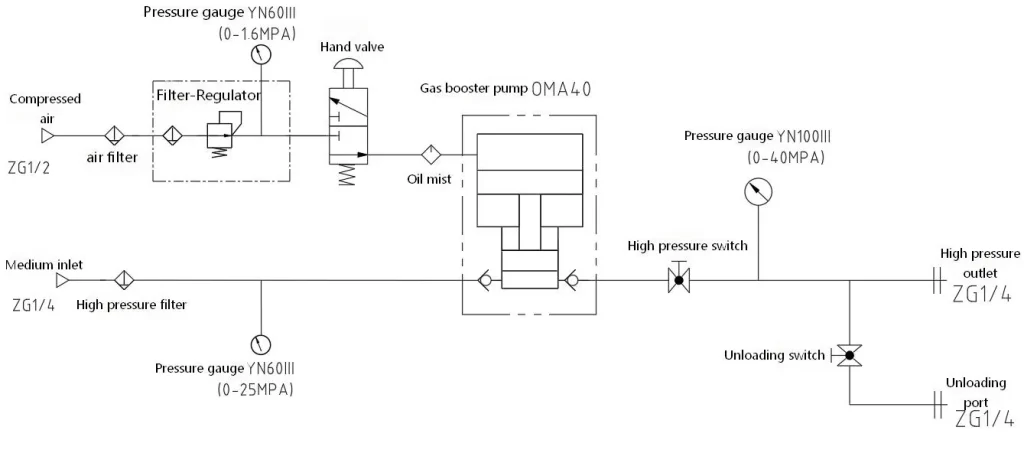
The Frame-Type Gas Booster System uses compressed air to drive a piston-type gas booster pump.
Compressed air enters the pneumatic drive section after filtration and pressure regulation. The pneumatic control valve alternately directs the drive air, causing the booster piston to reciprocate.
At the same time, process gas enters the gas section of the booster. Through repeated piston movement, the gas is compressed and discharged through the high-pressure outlet.
As outlet pressure rises, the piston reciprocating speed gradually decreases. When the pressure reaches the system equilibrium point, the booster stops automatically and consumes minimal drive energy.
If downstream pressure subsequently decreases, the booster restarts and replenishes the pressure until the required pressure level is restored. Pneumatic system quotation 260… Pneumatic system quotation 260…
Working process:
Compressed Air → Air Filtration & Regulation → Pneumatic Drive → OMA40 Gas Booster Pump → Gas Pressurization → High-Pressure Gas Outlet
Typical Applications
The MGS-OMA40 supplied configuration is designed for hydrogen gas boosting. Pneumatic system quotation 260…
For other projects, the appropriate booster model and system configuration should be selected according to the actual gas medium, inlet pressure, required outlet pressure, flow rate and operating conditions.
Typical gas booster systems can therefore be configured around different customer pressure requirements rather than treating the MGS-OMA40 parameters as universal specifications.
Customized Gas Booster Systems
Different gas boosting applications require different pressure ratios, flow capacities, materials, seals and control configurations.
To select a suitable Frame-Type Gas Booster System, please provide:
- Gas Medium
- Gas Inlet Pressure
- Required Outlet Pressure
- Required Flow Rate
- Operating Temperature
- Continuous or Intermittent Operation
- Manual or Automatic Control Requirements
Our team can configure the booster pump and integrated system according to the required operating conditions.
Contact Us For A Customized Gas Booster System Solution.




 English
 Français
 Русский
 Español
 Português
 العربية
 Tiếng Việt
 한국어
 Bahasa Indonesia
 Deutsch
 Türkçe
 Italiano